User Tools
Flash Floppy OSD for MSX

Русская версия находится здесь: Flash Floppy OSD для MSX
FlashFloppy is the well-known firmware for the Gotek floppy drive emulator by Keir Fraser. The firmware supports both the original Gotek's screen with three indicators, as well as OLED screens of various types. But few people in the MSX community (including me) knew that there had been also an addition to this firmware in the form of FlashFloppy OSD (On-Screen Display). This firmware is flashed into the STM32 microcontroller on the Blue Pill board, the board is connected to the Gotek and to two computer's video signals (one of color signals and to a composite sync signal) and as a result, a copy of the Gotek's screen is superimposed into the computer's video signal. This is very handy when Gotek does not have a screen, and also when the screen is not directly visible.
I first encountered the problem of “blind” switching of floppy disk images on a half-height Gotek (aka “slim”) when I was working on the DualSlim project. Due to the low height of the Gotek, it is very difficult to insert even the smallest screen into it. Yes, and it would be inconvenient to use it, since it would be on the side, and even under the overhanging body. I started looking for a way to solve this problem and found a project FlashFloppy OSD that has been around for several years and has been successfully applied on several vintage computers. But, as it turned out, this project was never adapted for MSX. After watching the video and documentation, I decided to become a pioneer.
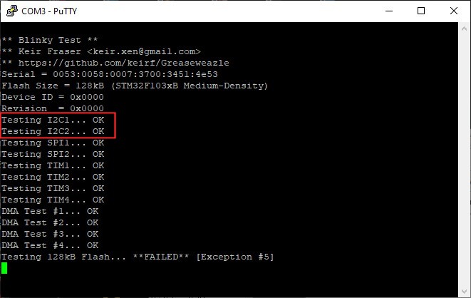
Like all pioneers, almost immediately I managed to step into a trap. It turned out that almost all Blue Pill boards do not contain original STM32 chips, but their Chinese-made clones. And these clones can't work properly with the latest FF OSD v1.9 firmware. Both boards that I purchased from a German distributor refused to pass the Blinker test - the I2C functionality did not work and the test also gave a warning about a fake chip. Then 4 more Blue Pill boards were ordered from China. One of them was again recognized as a fake by the test, while the rest did not pass the test due to the failure of the flashROM (most likely the size of the flashROM was incorrect). But at least they passed the I2C test. As a result, having spent almost 50 Euros, I received not quite suitable boards. But these 3 Chinese boards appeared to be OK after flashing FF OSD v1.9 into them. The boards were purchased here:
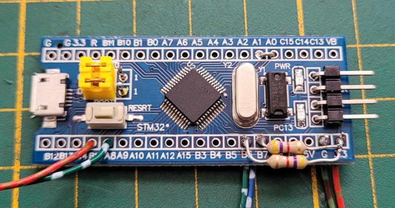
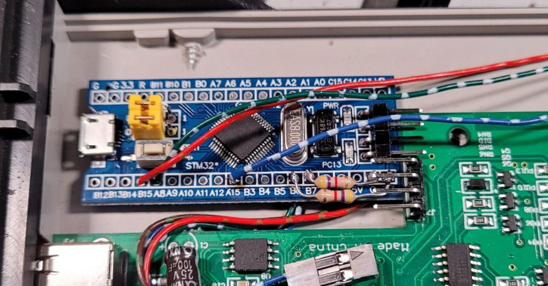
In the process of OSD project adaptation for MSX, my Gotek was slightly modified - a pin header was soldered to the power connector and I2C, and the latest FlashFloppy firmware was uploaded into it. Then I began tests with the Blue Pill board, that was installed in a modded Arabic AX-350 MSX2 computer. The Blue Pill board also had to be modified. I soldered 6 wires to it (using pin headers was out of the question because of tight space inside the slim Gotek), the height of the configuration jumpers was reduced (to fit in the slim case), and 4.7kOhm resistors were soldered to pull SDA and SCL signals to 3.3v. This is how it looks like:
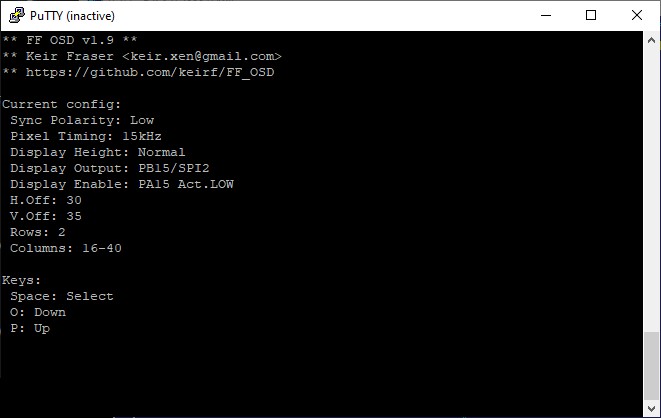
The jumper between A0 and A1 was initially soldered, but then it was removed, as it forces the increased size of the selected disk's name. It is better to make this jumper always removable, but I was not sure whether the board would fit into the slim Gotek's case. Then the board had to be configured - I connected it to the PC via UART, ran Putty, selected the port for communication and wrote the default settings into the flash memory. Then I slightly changed the coordinates of the OSD window output so that it was located in the upper left corner of the screen. The settings can be normally changed by controlling the board from the terminal window. A “space” entered in the terminal window selects an option, “P” or “O” select the value of the option. The correct configuration looks like this:
The first result (after repeated failures, several dozens of trial and error attempts) was achieved in a few days - the long-desired OSD finally appeared on the screen! The sync signal had to be connected from the computer's video module (there it has TTL levels, the board might not recognize weaker signals), the color signal for the OSD output was also “hooked up” there. But the OSD ended up with a bunch of color artifacts around the edges, as well as an increased height. Together with the author of the firmware, we tried to resolve the problem and as a result, after some modifications, we managed to display the OSD on the screen without artifacts and in the desired compact form. In this case, we removed the A0-A1 jumper on the Blue Pill board and installed a 330 Ohm resistor for the color channel. The test with the connected green RGB channel was the most successful, for other color channels the rest did not give very good color compatibility. Here is a color compatibility test's result:
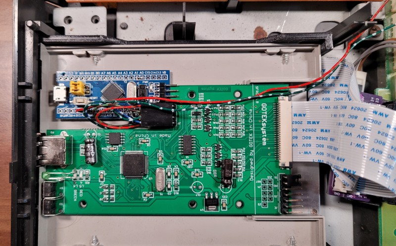
Then it turned out that the computer was losing the sync signal and color in the “Arabic” 50Hz PAL mode. Then a resistor to the sync signal line was added and set to 220 Ohm. After that everything worked as it should. In order for the OSD to turn off after a certain delay and not to stick out on the screen all the time, it is necessary to set the timeout “display-off-secs = N” in the FF.CFG file in the root of the USB flash drive, where N is the number of seconds until the OSD turns off, from 5 to 10 is just about right! This is how the installation and connection of the Blue Pill board with FF OSD firmware inside the slim Gotek's case looks like. I fixed the board inside with a not-so-thick double-sided tape:
Inside, you need to connect 3.3v power and ground to the Gotek's board, as well as connect SDA and SCL signals. When viewed from the side of the slim Gotek's connector, the outputs of the I2C interface look like this: [SDA] [SCL] [GND] [3.3v]. Here is a detailed video on how to flash the Blue Pill board and how to connect it to a full size Gotek's board - be sure to watch it before installing the board into your Gotek:
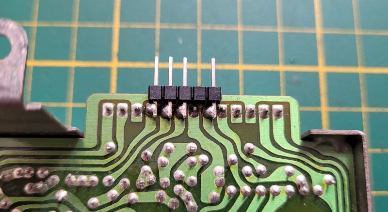
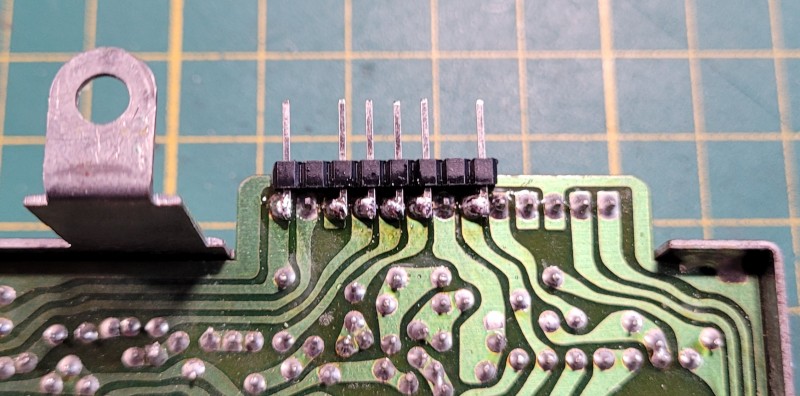
Only 2 wires needed to be brought out of the Gotek - one for outputting the OSD to a color channel and the second for inputting the sync signal to the Blue Pill board. The easiest way was to connect these wires directly to the input of the video module by soldering the pin header from below to its connector (only for AX-350, CX5M2, CX7, CX11, YIS503II, YIS503III):
To output wires from the Gotek, it is necessary to cut a small recess in its top cover:
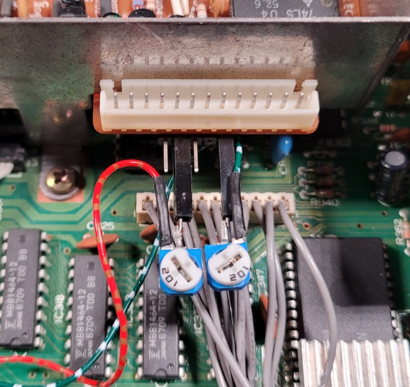
I used variable resistors so that I could find the right values, but you can immediately put the 330 Ohm on the color signal and 220 Ohm on the sync signal. This is how it looks in my setup:
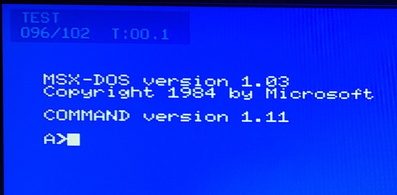
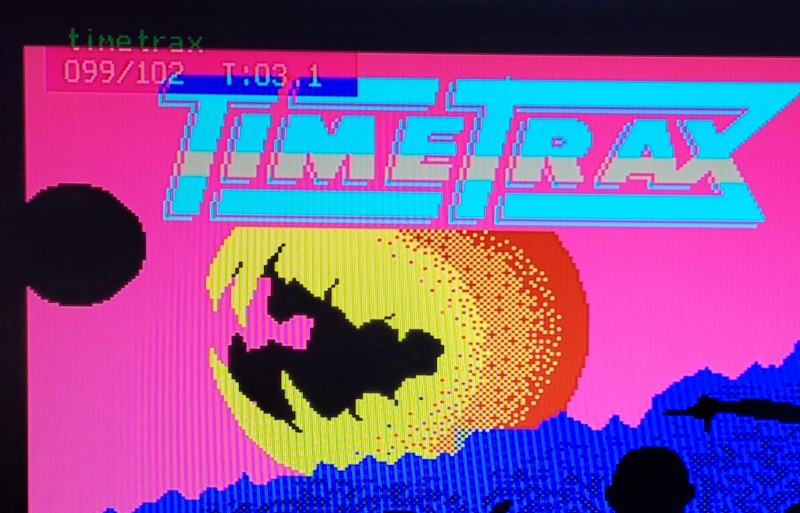
As a result, everything worked out fine and now the OSD is visible in all modes: in MSXDOS, BASIC and in games. Here are some screenshots:
Our discussion with the author of FF OSD firmware during my experiments could be found in : this ticket
But that wasn't all… :)
Perfectionism is sometimes a curse, but often leads to better results. Connecting the OSD to the green channel worked best, but as you can see in the color compatibility picture (see above), the OSD is not quite visible with some color combinations. It would be ideal to connect the OSD to all three color channels and even with the ability to make adjustments to each of them.
After talking to the author of the firmware, the idea to put diodes on the color channels was rejected, since the OSD is output by periodically pulling up the color signal either to the power or to the ground. As recommended by the author, it was decided to use the Hex 3-STATE buffer chip 74LS367. This required not only adding the additional wire to Gotek, but also re-configuring the FF OSD firmware. But let's do this one-by-one.
First, you need to change the configuration to activate the output A15 of the Blue Pill board to control the buffer chip. In the “Display Enable” option, you must select the value “PA15 Act.LOW”. It is best to do this at the very beginning of setting the board, if you have firmly decided to connect it to all three color channels. The correct configuration looks like this:
Then you need to solder a wire to pin A15 of the Blue Pill board and lead it out, as shown here:
Then you need to solder a a longer pin header (than described above) onto the video module's connector (only for AX-350 and similar computers), as shown here:
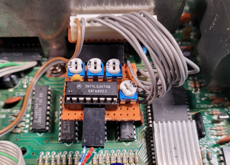
Now you need to assemble the simplest circuit with one microchip (74LS367 or 74HC367), four variable resistors (three 2kOhm each, one 1kOhm for the clock signal, but four 2kOhm will also do) and one ceramic capacitor (100nF). I assembled this circuit on a breadboard in just half an hour and connected it to the soldered pin headers of the video module. I connected the wires from Gotek to the breadboard with a three-pin connector:
The schematics of the board looks like this:
The board installed into the AX-350 looks like this:
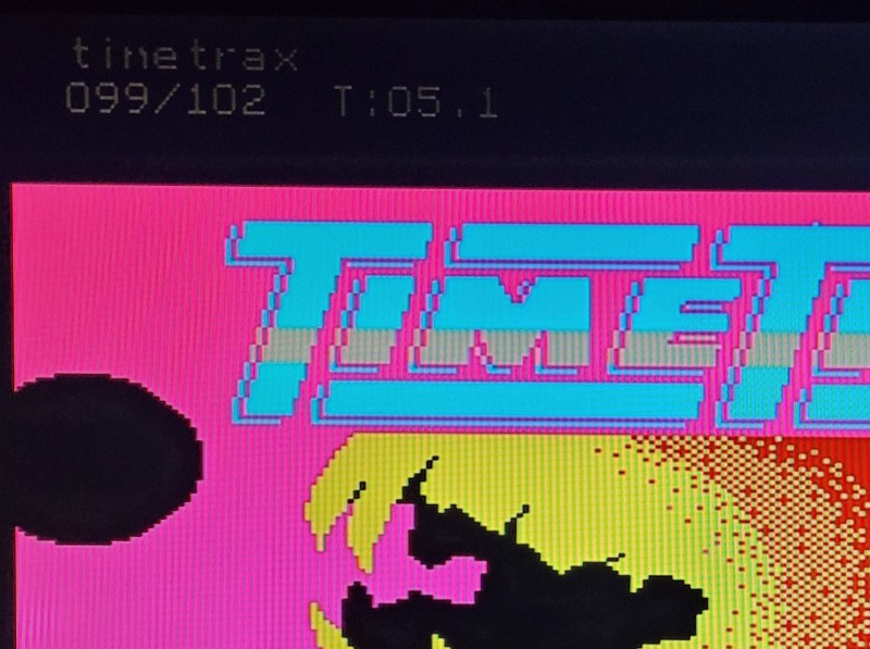
It should be noted that the outputs of the color channels require more resistance than for connecting a single channel (as described above). The resistance on the input line of the sync signal remains the same - 220 Ohm. By playing with the resistance values, we managed to get very good results. If the resistance is in the range of 700-800 Ohm, the black OSD frame almost overlaps the image below it and the text is 100% transparent, as seen here:
If you increase the resistance to 900 Ohm or more, then the OSD frame becomes translucent, as seen here:
If the text is shown on a black background, then the frame becomes invisible, but the text is displayed in gray color:
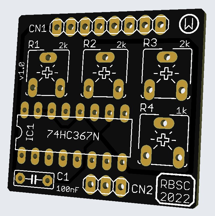
Anyway, let everyone choose the level of transparency of the OSD frame on his own. The main thing is not to set the resistance of the color lines below 700 Ohm. To facilitate the installation of the FF OSD, I made a special board that can be used not only in AX-350 and similar computers, but also in other MSX machines. The board will be released into the RBSC group's repository after I check it in action. Here's how it will look (its size is only 3x3cm):
This small board can be also used to connect only one color channel, without installing a microchip. In this case, a variable resistor is placed on the desired channel and the soldering points of the microchip's pins corresponding to this channel are connected by a jumper. For example, for the green channel, only R2 is placed and the pins 4 and 5 are bridged (pins 2 and 3 for the red channel, pins 6 and 7 for the blue channel). The variable resistor R4 is always installed. In this case, only wires from B15 (middle pin of CN2) and from A8 (right pin of CN2) of the Blue board are connected.
If anyone has any questions about installing and configuring the FF OSD in MSX - send me an e-mail or write your question here.
Finally, the project is complete! The official firmware FlashFloppy v3.36 now allows to control the size and contents of the OSD. Big thanks to Keir Fraser for his excellent work!
In the previous post there was some info about the A0-A1 jumper. Well, this jumper is required, so please solder it onto the board. Now you can control FF OSD using the Gotek's buttons. Pressing two buttons at the same time is equal to selecting an option or confirming an operation (for example saving the configuration). Pressing either button will allow to go up or down the list of available options or changing a value of a selected option (for example setting the offset of OSD relative to the upper left corner of the screen).
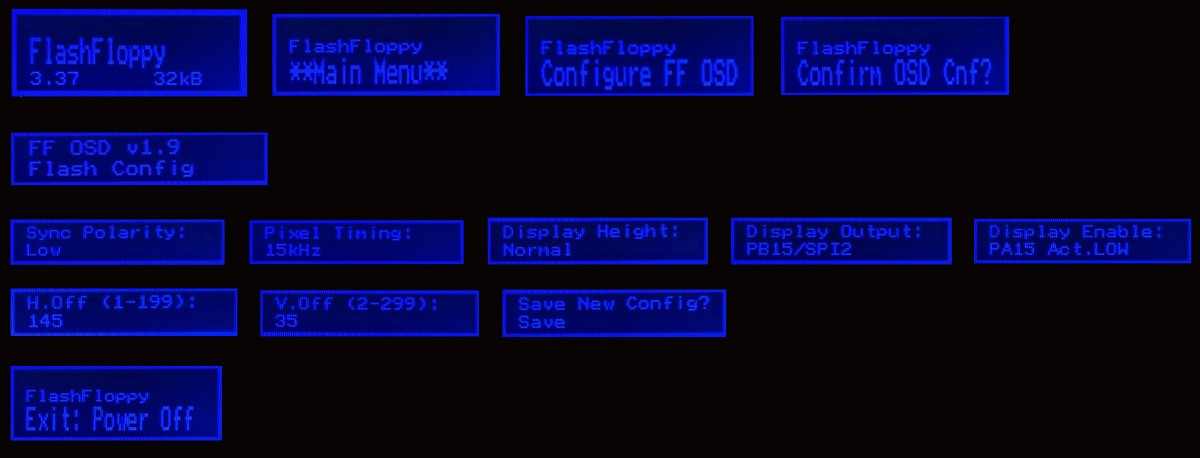
To configure FF OSD, first remove USB stick from Gotek and power on the computer. By pressing 2 buttons, enter the main menu and select the option to configure FF OSD. Confirm the operation with 2 buttons pressed at the same time. Then, enter the configuration menu and set the following values:
Sync Polarity: Low
Pixel Timing: 15kHz
Display Height: Normal
Display Output: PB15/SPI2
Display Enable: PA15 Act.LOW
The last option is obligatory if you connected your Blue Pill board to 3 color channels using the FF OSD 2CH BOARD. Now you can choose the location of the OSD on your screen. It's best to put it in the upper right corner of the screen. The values of the screen offset should be set as follows:
H.Off (1-199): 145
V.Off (2-299): 35
Finally, confirm saving the configuration into FlashROM of the Blue Pill by pressing 2 buttons at the same time. Wait for the message about power-off and switch off the computer. After switching the computer on again, the FF OSD configuration will be taken into use and will work as you desire. That's how configuration options look like on a screen:
The last thing to do is to put the properly set FF.CFG configuration file to the root folder of your USB drive. This file comes with every new firmware and it contains new options that the latest firmware supports. To use Gotek with FF OSD the following options are recommended for FF.CFG:
host = msx
display-type = auto
oled-font = 6x13
display-order = default
osd-display-order = 0,1
osd-columns = 16
display-off-secs = 5
The last option allows to control the timeout of the OSD (delay before it disappears, in seconds). It's recommended to set it to 5 seconds, so that it doesn't stay on for long and bother you while you are playing or working with DOS. The configuration file for FlashFloppy v3.36 and later firmware version can be found here:
FF.CFG
Save this file into the root folder of your USB drive, insert it into Gotek and power on. Now you have FF OSD ready and properly configured. You can also move it to any desired place on the screen. That's how it should look like:
The Gerber files for the FF OSD 3CH BOARD can be found here (commercial usage is not allowed!):
ffosd_board_gerber_10.zip
As not all Blue Pill boards can be used for the FF OSD project, it recommended to test your board before installing it into Gotek. This can be done by uploading the Blinky firmware into the board. The very last firmware has non-standard bitrate, so we recommend to use an earlier version (115200 baud rate):
The Blinky test may not fully succeed on your Blue Pill board, but at least I2C interface test must pass:
[b]If you liked the project, please feel free to send a few bucks to the author of the FlashFloppy and FF OSD firmware in appreciation of his efforts and patience.[/b]
